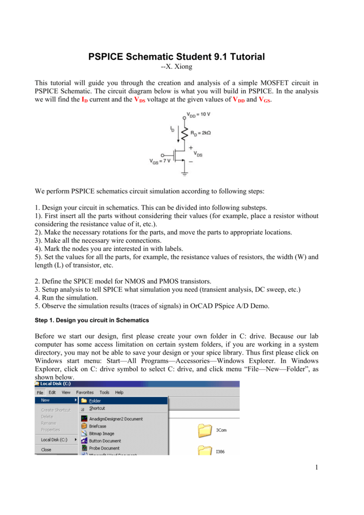

If you have the OrCAD software installed, launch Capture or Capture CIS, by clicking on: For this book, it does not matter whether the circuits are drawn in Capture or Capture CIS. The CIS option, which stands for Component Information System, allows you to select and place components from a component database instead of selecting and placing components from a library. (The procedure required to create entirely new models is beyond the scope of this text but is described in some of the references listed in Appendix C.)ĭennis Fitzpatrick, in Analog Design and Simulation using OrCAD Capture and PSpice, 2012 1.1 Starting CaptureĬircuit diagrams for PSpice simulation are drawn in either Capture or Capture CIS schematic editor.

Repeat this procedure for the other three diodes.

Change the “By” variable from 100 to 200 and then push the “OK” button. A “Model Editor” dialog box will appear that will list all the parameters of the model. ( Note: if we were to use real D1N4148's in this bridge, exceeding the reverse breakdown voltage would most likely cause them to burn out with potentially dire consequences!) Click on a diode to select it and from the “Edit” drop-down menu select “Model.” In the “Edit Model” dialog box that appears, push the “Edit Instance Model” button. Since we are using a voltage source with a maximum voltage of 169.7 V, we will change the breakdown voltage of the model to 200 V. For this diode, the model has this breakdown voltage set to By = 100 V. It suffices to say that while an ideal diode has zero current for any voltage applied across it in the “wrong” direction, a real diode has a maximum reverse breakdown voltage that should not be exceeded. The modeling of this element is a subject for an electronics course, but we need to make one simple modification nonetheless. The only elements in this circuit that we have not yet considered in previous examples are the four identical diodes, which have the part name “D1N4148” and can be found in the “eval.slb” library. The PSpice schematic for the filtered full-wave diode rectifier. All of the switch default values were used for this simulation.įigure 7.57. The final parameter is “ttran,” which is the time it takes to make the transition from the high-impedance state to the low-impedance state. The “tClose” variable indicates the time when the switch begins to change from its open state to its closed state. In particular, care should be taken if either of these values is the same order of magnitude as other resistances in the circuit. The default values are given in the dialog box and can be changed if necessary. However, for numerical reasons and because some switches are nonideal, the switch model has the parameters Ropen and Rclosed to model the nonideal open and closed resistances of the switch, respectfully. An ideal switch is modeled by infinite open resistance and zero closed resistance. The first property is the Package Reference Designator “PKGREF” (i.e., name) which uniquely identifies each part that is placed in the circuit. There are five properties of this model that can be adjusted. The properties of the switch can be found by double-clicking on the switch after it has been placed in the circuit. Pressing the “OK” button will select the switch and it can then be placed on the schematic in the usual way.

This name will appear in the “Part Name” box at the top of the window and the description “Switch: closes at tClose= ?” will appear directly below the part name box. The switch required for this example can be found by clicking on the “eval.slb” library (using the scroll bars if necessary) and scrolling down the parts list until the name “Sw_tClose” is visible. That button brings up the “Get Part” dialog box that lists the various libraries that contain the part models and lists the parts contained in whichever library is highlighted. If one is uncertain of the name of a circuit model or even uncertain if a model exists, one can press the “Browse…” button in the “Add Part” dialog box for help. The part name for the switch is “Sw_tClose,” which can be accessed by typing this name in the “Add Part” dialog box. The PSpice schematic for the circuit in Example 7.5. * From section of C:\Users\lenovo\AppData\Roaming\SPB_Data\cdssetup\OrCAD_PSpice/16.6.0/PSpice.ini file: ** WARNING: THIS AUTOMATICALLY GENERATED FILE MAY BE OVERWRITTEN BY SUBSEQUENT SIMULATIONS I am new to orcad pspice simulation,when i try to simulate the isolation amplifier(AMC1300) ,i got the error like floating node and less the two connections, but i connect power symbols and gnd ref (0) properly,what i do?


 0 kommentar(er)
